A complete test environment for automated production and integration test of
RF components and modules
A Complete RF Test Environment
- Delivered ready to test with a fully featured execution and development environment
- Full set of common RF measurements
- Fully integrated Device Under Test (DUT) power and multi-state control
- Fully integrated control of peripherals such as temperature chambers
- Architected to support ATE
True Synthetic Architecture
- Utilizes a common set of hardware for all stimulus and response functions
- Smaller footprint than traditional “rack and stack” instruments
- Mature system level calibration scheme
- Reduced hardware cost compared to full instrument-based test system
- New capability can be added incrementally at low cost with little impact to existing measurement sequences
Complex Device Testing Capable
- Frequency range 1 MHz to 6 GHz (expandable to 32 GHz)
- Complete measurement suite including S-parameters for full characterization of devices such as LNAs, VCOs and transceiver modules.
- Control of device states built into measurements
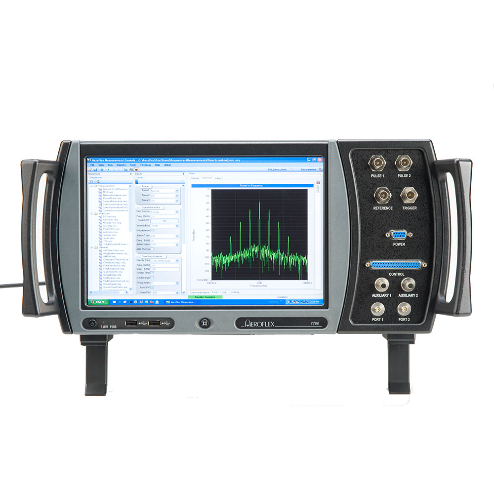
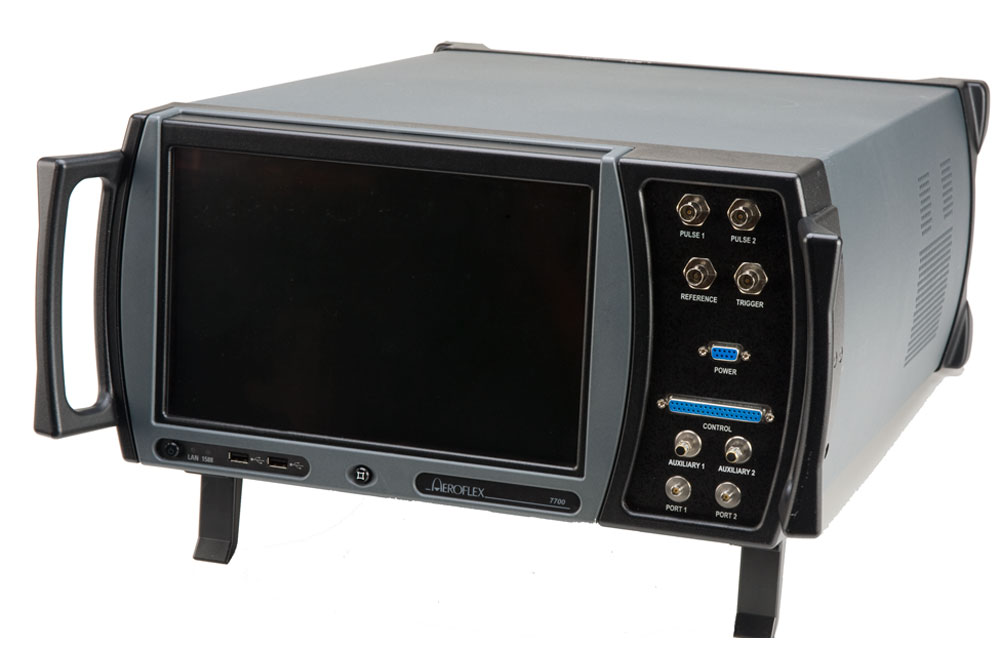
The 7700 Integrated Microwave Test Solution provides RF component, module and system manufacturers an advanced and flexible test environment to meet today’s requirements and tomorrow’s challenges. By leveraging the architecture of the synthetic product family and hardware from the Aeroflex Common Platform product line, the 7700 offers unprecedented capability in a condensed footprint.
The 7700 provides best-in-class performance up to 6 GHz for the most demanding RF testing applications. The 7700’s unique synthetic architecture allows for measurement throughput several times faster than rack and stack. It also comes standard with several built-in measurement, test executive and reporting tools to accelerate automated test development. Many additional measurement personalities are also available from Aeroflex or may even be developed by the end user.
The 7700 provides the most capable, flexible and scalable synthetic test instrumentation with the lowest cost of ownership in the industry. While the base model is fully featured, our state-of-the-art modular hardware and software components allow a 7700 to be configured with options to provide a total measurement solution with unmatched operational efficiency, upgrade capability and obsolescence protection.
| 7700 PRODUCT SPECIFICATIONS | ||||
| There are multiple options for the 7700 for frequency coverage, output power and signal multiplexing. The specifications for the 7700 are dependent on the various system options. The key specifications for the 7700 are specified in separate tables based on frequency coverage. | ||||
| STIMULUS (6 GHz) | ||||
| Frequency Range | 1 MHz — 6 GHz | |||
| Frequency Resolution | ||||
| 1 MHz to 3 GHz | 1 Hz | |||
| 3 to 6 GHz | 2 Hz | |||
| Output Power | 0 dBm (options for +15 dBm) | |||
| Output Power Range | >100 dB | |||
| Output Power Resolution | 0.02 dB | |||
| Frequency Switching Times | <1 msec=»» td=»»> | |||
| RF Modulation BW | 90 MHz | |||
| Dual Channel AWG Memory (Options to 512 Msamples) | 128 Msamples | |||
| Modulation Types | AM, FM, PM, Pulse, Vector (loaded waveform) | |||
| Phase Noise (2 GHz, 20 KHz offset) | -115 dBc/Hz | |||
| Spurious (>10 KHz offset, CW) | -70 dBc typical | |||
| PULSE MODULATION | ||||
| Rise/Fall Time | <10 nsecs=»» td=»»> | |||
| Minimum Pulse Width | 20 nsecs | |||
| Maximum PRF | 5 MHz | |||
| On/Off Ratio | 80 dB Typical | |||
| NOISE SOURCE | ||||
| ENR (10 MHz to 3 GHz) | 20 dB | |||
| ENR (3 to 6 GHz) | 15 dB | |||
| Level Control | 31 dB | |||
| RESPONSE (6 GHz) | ||||
| Frequency Range | 1 MHz to 6 GHz | |||
| Instantaneous BW | 90 MHz | |||
| Digitizer | 14 bits, 250 MS/sec | |||
| Sample Memory | Up to 512 MByte | |||
| Residual Noise Floor | <-100 dbm=»» td=»»> | |||
| Maximum Input Power | +28 dBm | |||
| Input Attenuator | 0 to 30 dB, 10 dB steps | |||
| Frequency Switching Times | <1 msec=»» td=»»> | |||
| Phase Noise (2 GHz, 20 kHz offset) | -110 dBc/Hz | |||
| Spurious (>10 KHz offset, CW) | -75 dBc typical | |||
| GENERAL MEASUREMENTS (6 GHz) | ||||
| POWER | ||||
| Frequency Range | 1 MHz to 6 GHz | |||
| Modes | Tone power, total power | |||
| Amplitude Uncertainty | ±0.25 dB (to -50 dBm) | |||
| FREQUENCY | ||||
| Frequency Range | 1 MHz to 6 GHz | |||
| Modes | CW, modulated | |||
| Frequency Resolution | 1 Hz | |||
| Sensitivity | -60 dBm | |||
| Time Base Accuracy | See Frequency Reference | |||
| NOISE FIGURE | ||||
| Frequency Range | 10 MHz to 6 GHz | |||
| Measurement Uncertainty | 0.3 dB | |||
| TIME DOMAIN | ||||
| Frequency Range | 1 MHz to 6 GHz | |||
| Sensitivity | -60 dBm | |||
| Resolution | 4 nsecs | |||
| VECTOR NETWORK ANALYSIS (6 GHz) | ||||
| Frequency Range | 100 MHz to 6 GHz | |||
| Modes | CW, pulsed | |||
| S21 Amplitude Uncertainty | 0.125 dB (10 dB insertion loss) | |||
| S21 Phase Uncertainty | 1.5 deg (10 dB insertion loss) | |||
| S11 Reflection Coefficient Uncertainty | 0.015 (Linear) | |||
| Dynamic Range | >100 dB | |||
| SPECTRUM (6 GH) | ||||
| Frequency Range | 1 MHz to 6 GHz | |||
| Resolution Bandwidth Range | 1 Hz to 10 MHz | |||
| Video Bandwidth Range | RBW / N (1 < N < 65536) N in powers of 2 | |||
| Reference Level Range | +28 dBm to noise level | |||
| Amplitude Resolution | 0.02 dB | |||
| RELATIVE POWER UNCERTAINTY | ||||
| Input Level >-60 dBm | 0.5 dB | |||
| -90 dBm < Input Level <-60 dbm=»» td=»»> | 1.0 dB | |||
| Spurious Free Dynamic Range | 75 dB nominal | |||
| DANL (1 Hz res bandwidth) | ||||
| 1 MHz to 2 GHz | -150 dBm/Hz | |||
| 2 to 4 GHz | -145 dBm/Hz | |||
| 4 to 6 GHz | -140 dBm/Hz | |||
| AC INPUT POWER (6 GHz) | ||||
| Input Voltage (Single Phase) | 100 to 250 VAC 47 to 63 Hz |
|||
| Mains Supply Voltage Fluctuations | <10% of=»» the=»» nominal=»» voltage=»» td=»»> | |||
| Fuse Requirements | 10A, 250V, Type F | |||
| DIMENSIONS AND WEIGHT (6 GHz) | ||||
| Height | 20.32 cm (8 in.) | |||
| Width | 44.45 cm (17.5 in.) | |||
| Depth | 60.96 cm (24 in.) | |||
| Weight | 25 kg (52 lbs.) | |||
| GENERAL (ALL CONFIGURATIONS) | ||||
| DUT CONTROL | ||||
| Number of Bits | 32 | |||
| Logic Level | LVDS | |||
| Clock Rate | Up to 100 MHz | |||
| TIMING SIGNAL GENERATION | ||||
| Number of Pulses | 6 | |||
| Resolution | 0.1 nsecs | |||
| Pulse Repetition Interval Max/Min | 1 Hz to 5 MHz | |||
| Pulse Repetition Interval Resolution | 20 nsecs | |||
| FREQUENCY REFERENCE (Requires 10 MHz option) | ||||
| Frequency | 10 MHz | |||
| Modes | Internal/external | |||
| Temperature Range | 0°C to 50°C | |||
| Warm-up Time | 10 min. | |||
| Temperature Stability | <0.01 ppm=»» typical=»» td=»»> | |||
| Aging | 0.001 ppm per day 0.01 ppm per year |
|||
| DC Power Supply | Multiple options available | |||
| ENVIRONMENTAL (ALL CONFIGURATIONS) | ||||
| Operating Temperature1 | 0 to 50°C (single 7700 chassis) 0 to 40°C (complete system in rack) |
|||
| Storage Temperature1 | -40 to 71°C | |||
| Warm Up Time | 30 min. | |||
| Relative Humidity1 | 80% up to 31°C decreasing linearly to 50% at 40°C | |||
| Altitude1 | 4.600 m (15, 092 ft) | |||
| Shock and Vibration1 | 30 G Shock (Functional Shock) 5-500 Hz random vibrations | |||
| Use | Pollution degree 2 | |||
| Safety Standards | EN 61010-1, IEC 61010-1 | |||
| EMC | Mil-PRF-28800F EN 61326-1: Class A EN61000-3-2 EN61000-3-3 | |||
| 1 Tested in accordance with MIL-PRF-28800F Class 3 | ||||
| STIMULUS (ANALOG SOURCE) | ||||
| Frequency Range | ||||
| 20 GHz Option: | 1 MHz to 20 GHz | |||
| 32 GHz Option: | 1 MHz to 31.8 GHz | |||
| Frequency Resolution | 1 Hz | |||
| Output Power (Excluding RF MUX loss, other power options available) | ||||
| 1 MHz to 20 GHz | +10 dBm | |||
| 20 to 31.8 GHz | +5 dBm | |||
| Output Power Range | >100 dB | |||
| Output Power Resolution | 0.01 dB | |||
| Frequency Switching Times | <1 msec=»» td=»»> | |||
| Modulation Types | AM, FM, PM, Pulse | |||
| Pulse Modulation | ||||
| Rise/Fall Time | <10 nsecs=»» typical=»» td=»»> | |||
| Minimum Pulse Width | 20 nsec | |||
| Maximum PRF | 5 MHz | |||
| On/Off Ratio | 80 dB | |||
| Calibration Uncertainty (No RF MUX) | ||||
| 0.1 to 20 GHz | 0.2 dB | |||
| 20 to 32 GHz | 0.3 dB | |||
| Calibration Uncertainty (With 12 Port MUX) | ||||
| 0.1 to 20 GHz | 0.3 dB | |||
| 20 to 32 GHz | 0.4 dB | |||
| Internal 10 MHz Reference Stability | <±1 ppm=»» year=»» with=»» optional=»» td=»»> | |||
| Spurious (>10 KHz offset, CW) | -60 dBc typical | |||
| Harmonics | -50 dBc (typical, F >=2 GHz) -50 dBc (typical, F <2 ghz=»» -10=»» dbm=»» td=»»> |
|||
| STIMULUS PHASE NOISE (32 GHz MICROWAVE ANALOG SOURCE) | ||||
| Offset (Hz) | 1 GHz | 10 GHz | 20 GHz | 30 GHz |
| (dBc/Hz) | (dBc/Hz) | (dBc/Hz) | (dBc/Hz) | |
| 10 | -54 | -38 | -30 | -25 |
| 100 | -103 | -82 | -75 | -70 |
| 1000 | -117 | -95 | -91 | -84 |
| 10000 | -122 | -102 | -95 | -91 |
| 100000 | -122 | -103 | -97 | -91 |
| 1000000 | -145 | -128 | -122 | -115 |
| 10000000 | -160 | -147 | -140 | -134 |
| STIMULUS (32 GHz MICROWAVE VECTOR SOURCE) | ||||
| Frequency Range | 1 MHz to 31.8 GHz | |||
| Frequency Resolution | 1 Hz | |||
| Output Power (Excluding RF MUX loss, other power options available) | ||||
| 1 MHz to 20 GHz | +10 dBm | |||
| 20 to 31.8 GHz | +5 dBm | |||
| Output Power Range | >100 dB | |||
| Output Power Resolution | 0.01 dB | |||
| Frequency Switching Times | <10 msec=»» td=»»> | |||
| RF Modulation BW | 80 MHz (other options available for larger bandwidths) | |||
| Waveform Memory | 64 Msamples | |||
| Modulation Types | AM, FM, PM, Pulse, Vector (loaded waveform) | |||
| Pulse Modulation | ||||
| Rise/Fall Time | <10 nsecs=»» td=»»> | |||
| Minimum Pulse Width | 150 nsecs (20 nsec optional) | |||
| Maximum PRF | 5 MHz | |||
| On/Off Ratio | 80 dB | |||
| Calibration Uncertainty (No RF MUX) | ||||
| 0.1 to 20 GHz | 0.2 dB | |||
| 20 to 32 GHz | 0.3 dB | |||
| Calibration Uncertainty (With 12 Port MUX) | ||||
| 0.1 to 20 GHz | 0.3 dB | |||
| 20 to 32 GHz | 0.4 dB | |||
| Spurious (>10 KHz offset, CW) | -60 dBc typical | |||
| Harmonics | -50 dBc (typical) | |||
| Internal 10 MHz Reference Stability | <±3 x=»» 10-8=»» year=»» or=»» br=»»> <±2.5 x=»» 10-10=»» day=»» after=»» 30=»» days=»» td=»»> | |||
| STIMULUS PHASE NOISE (32 GHz MICROWAVE VECTOR SOURCE) | ||||
| Offset (Hz) | 1 GHz | 10 GHz | 20 GHz | 30 GHz |
| (dBc/Hz) | (dBc/Hz) | (dBc/Hz) | (dBc/Hz) | |
| 10 | -100 | -80 | -70 | -70 |
| 100 | -112 | -92 | -86 | -83 |
| 1000 | -133 | -114 | -110 | -105 |
| 10000 | -145 | -130 | -121 | -115 |
| 100000 | -146 | -130 | -121 | -115 |
| 1000000 | -150 | -158 | -138 | -130 |
| 10000000 | -150 | -160 | -151 | -145 |
| RESPONSE (32 GHz) | ||||
| Frequency Range | 1 MHz to 31.8 GHz | |||
| Instantaneous BW | 90 MHz (Higher bandwidth options available) | |||
| Digitizer | 14 bits, 250 MS/sec | |||
| Residual Noise Floor | <-110 dbm=»» td=»»> | |||
| Maximum Input Power | +30 dBm Average (no RF MUX) +45 dBm Average (with optional RF MUX) +51 dBm Pulsed (20% duty cycle, with optional RF MUX) |
|||
| Input Attenuator | 0 to 90, 10 dB steps | |||
| Frequency Switching Times | <1 msec=»» td=»»> | |||
| Spurious (>10 KHz offset, CW) | -70 dBc typical | |||
| RESPONSE PHASE NOISE (32 GHz) | ||||
| Offset (Hz) | 3 GHz | 10 GHz | 20 GHz | 30 GHz |
| (dBc/Hz) | (dBc/Hz) | (dBc/Hz) | (dBc/Hz) | |
| 10 | -67 | -56 | -50 | -47 |
| 100 | -97 | -86 | -80 | -77 |
| 1000 | -118 | -107 | -101 | -98 |
| 10000 | -126 | -115 | -109 | -106 |
| 100000 | -128 | -117 | -111 | -108 |
| 1000000 | -137 | -126 | -120 | -117 |
| 10000000 | -147 | -136 | -130 | -127 |
| GENERAL MEASUREMENTS (32 GHz) | ||||
| POWER MEASUREMENT | ||||
| Frequency Range | 1 MHz to 31.8 GHz | |||
| Measurement Uncertainty | ||||
| (Power >-50 dBm, No RF MUX) | ||||
| 0.1 to 20 GHz | 0.2 dB | |||
| 20 to 26.5 GHz | 0.3 dB | |||
| 26.5 to 32 GHz | 0.4 dB | |||
| Measurement Uncertainty | ||||
| (Power >-50 dBm, With 12 Port MUX) | ||||
| 0.1 to 20 GHz | 0.25 dB | |||
| 20 to 26.5 GHz | 0.4 dB | |||
| 26.5 to 32 GHz | 0.5 dB | |||
| Resolution | 0.1 dB | |||
| FREQUENCY | ||||
| Frequency Range | 1 MHz to 31.8 GHz | |||
| Modes | CW, modulated | |||
| Frequency Resolution | 1 Hz | |||
| Sensitivity | -60 dBm | |||
| Time Base Accuracy | See Frequency Reference | |||
| NOISE FIGURE | ||||
| Frequency Range | 10 MHz to 31.8 GHz | |||
| Resolution | 0.01 dB | |||
| Measurement Uncertainty (No RF MUX) | ||||
| 10 MHz to 20 GHz | 0.3 dB | |||
| 20 GHz to 32 GHz | 0.5 dB | |||
| Measurement Uncertainty (RF MUX) | ||||
| 10 MHz to 20 GHz | 0.5 dB | |||
| 20 GHz to 32 GHz | 1.0 dB | |||
| TIME DOMAIN | ||||
| Frequency Range | 1 MHz to 31.8 GHz | |||
| Sensitivity | -60 dBm | |||
| Resolution | 4 nsecs | |||
| Risel/Fall Time | ±20 nsecs | |||
| Droop | 0.1 dB minimum 0.1 dB resolution |
|||
| VECTOR NETWORK ANALYSIS | ||||
| Frequency Range | 500 MHz to 40 GHz (with appropriate source and response options) | |||
| Modes | CW, Pulsed | |||
| S21 Amplitude Uncertainty (±) (at 10 dB insertion loss) (No RF MUX) | ||||
| 50 MHz to 20 GHz | 0.125 dB | |||
| 20 to 26.5 GHz | 0.25 dB | |||
| 26.5 to 32 GHz | 0.25 dB | |||
| S21 Amplitude Uncertainty (±) (at 10 dB insertion loss) (with RF MUX) | ||||
| 50 MHz to 20 GHz | 0.2 dB | |||
| 20 to 26.5 GHz | 0.4 dB | |||
| 26.5 to 32 GHz | 0.4 dB | |||
| S21 Phase Uncertainty (±) (at 10 dB insertion loss) (No RF MUX) | ||||
| 50 MHz to 20 GHz | 1.5 deg | |||
| 20 to 26.5 GHz | 2.0 deg | |||
| 26.5 to 32 GHz | 3.0 deg | |||
| S21 Phase Uncertainty (±) (at 10 dB insertion loss) (With RF MUX) | ||||
| 50 MHz to 20 GHz | 2.0 deg | |||
| 20 to 26.5 GHz | 2.8 deg | |||
| 26.5 to 32 GHz | 4.0 deg | |||
| S11 Reflection Coefficient Uncertainty (±, Linear) (No RF MUX) | ||||
| 50 MHz to 20 GHz | 0.015 | |||
| 20 to 26.5 GHz | 0.020 | |||
| 26.5 to 32 GHz | 0.025 | |||
| S11 Reflection Coefficient Uncertainty (±, Linear) (With RF MUX) | ||||
| 50 MHz to 20 GHz | 0.020 | |||
| 20 to 26.5 GHz | 0.030 | |||
| 26.5 to 32 GHz | 0.035 | |||
| Dynamic Range | >110 dB | |||
| SPECTRUM (32 GHz) | ||||
| Frequency Range | 1 MHz to 31.8 GHz | |||
| Resolution Bandwidth Range | 1 Hz to 10 MHz | |||
| Video Bandwidth Range | RBW/ N (1 < N < 65536) N in powers of 2 |
|||
| Reference Level Range | +30 dBm to noise level (Higher power supported with RF MUX as listed in RESPONSE section) | |||
| Amplitude Resolution | 0.02 dB | |||
| RELATIVE POWER UNCERTAINTY | ||||
| Input Level >-60 dBm | 0.5 dB | |||
| -90 dBm < Input Level <-60 dbm=»» td=»»> | 1.0 dB | |||
| -100 dBm < Input Level <-90 dbm=»» td=»»> | 2.0 dB | |||
| Spurious Free Residual Noise Floor | <-110 db=»» td=»»> | |||
| DANL (1 Hz Bandwidth) | ||||
| 3 to 20 GHz | -150 dBm/Hz | |||
| 20 to 26.5 GHz | -145 dBm/Hz | |||
| 26.5 to 32 GHz | -140 dBm/Hz | |||
| Spurious Free Dynamic Range | 75 dB (nominal) | |||
| AC INPUT POWER (32 GHz) | ||||
| Input Voltage (Single Phase) | 230 VAC, 50 Hz 110 VAC, 60 Hz |
|||
| Mains Supply Voltage Fluctuations | <10% of=»» the=»» nominal=»» voltage=»» td=»»> | |||
| Power Consumption | Depends on options | |||
| DIMENSIONS AND WEIGHT (32 GHz) | ||||
| Height | ||||
| Depends on options | ||||
| Width | ||||
| Depends on options | ||||
| Depth | ||||
| Depends on options | ||||
| Weight | ||||
| Depends on options | ||||
| SYSTEM OPTIONS | ||||
| item | Description | |||
| Base 7700 Unit — 3 GHz | Stimulus and response coverage to 3 GHz +5 dBm stimulus output power 90 | |||
| MHz | instantaneous BW on stimulus | |||
| and | response | |||
| AWG based stimulus signal geneation, 128 Msamples waveform memory Stimulus modulation (AM, FM, PM, Pulse, loaded waveform) | ||||
| Includes Aeroflex Maintenance Console with instrument panels Analog and vector source Spectrum analyzer Network analyzer Noise figure meter |
||||
| Frequency Extension to 6 GHz | Extension of stimulus and response frequency coverage to 6 GHz | |||
| Frequency Extension to 20 GHz | Extension of stimulus and response frequency coverage to 20 GHz | |||
| Frequency Extension to 32 GHz | Extension of stimulus and response frequency coverage to 32 GHz | |||
| High Power Option | High power option for stimulus (+15 dBm at 6 GHz) | |||
| 6 Port RF Mux (6 GHz) | Addition of external 6 port RF Multiplexer to 6 GHz | |||
| 2 port RF Mux and S-parameter with test set | Addition of external 2 port RF Multiplexer Test Set (26.5 GHz) integral S-parameter | |||
| 12 port RF Mux and S-parameter with | Addition of external 12 port RF Multiplexer | |||
| Test Set (26.5 GHz) | integral S-parameter test set | |||
| DUT Digital Control | Additional of Digital Control module, 32 bits LVDS, 100 MHz clock rate Example DUT.dll | |||
| 10 MHz Reference | Addition of high stability 10 MHz reference | |||
| DUT DC Power | Multiple options available for DUT DC Power | |||
| UPS | Addition of uninterruptible power supply | |||