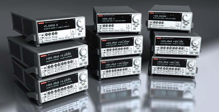
- Содержат в себе: программируемый источник напряжения, программируемый прецизионный источник тока, цифровой мультиметр, генератор сигналов произвольной формы, импульсный генератор напряжения и тока с функцией измерения, электронную нагрузку и контроллер запуска
- Изделия указанной серии перекрывают широкий динамический диапазон: от 1 фА до 50 А и от 1 мкВ до 200 В
- Скорость до 20 000 измерений в секунду позволяет сократить время тестирования и регистрировать переходные процессы в устройствах
Программное обеспечение:
- TSP® Express обеспечивает быстрое и удобное измерение тока и напряжения (встроенное ПО)
- ACS Basic Edition для измерения характеристик полупроводниковых компонентов (по дополнительному заказу)
Источники-измерители серии 2600B – это новейшие источники-измерители компании Keithley, которые могут применяться как в настольном исполнении, так и в качестве модулей для построения многоканальных систем. Реализованная в изделиях серии 2600B архитектура на основе встроенного процессора сценариев тестирования (TSP) в сочетании с возможностями проведения параллельного тестирования и точной синхронизации обеспечивают самую высокую в отрасли производительность и низкую стоимость тестирования. При настольном применении в источниках-измерителях серии 2600B устанавливается встроенное программное обеспечение TSP Express или дополнительно приобретаемые программные средства для измерения характеристик компонентов к ACS Basic.

Встроенное ПО тестирования, написанное на Java, для повышения производительности позволяет работать с любого браузера.
Типовые сферы применения:
- Функциональное тестирование, связанное с измерением тока и напряжения и снятием характеристик для широкого спектра устройств, в том числе:
- дискретных и пассивных компонентов;
- интегральных устройств, включая компоненты с низкой (SSI) и высокой (LSI) степенями интеграции;
- оптоэлектронных приборов, таких как светодиоды, лазерные диоды, сверхяркие светодиоды (HBLED), полупроводниковые лазеры с вертикальным резонатором и поверхностным излучением (VCSEL), дисплеи;
- испытания на надежность на уровне кристалла, например, тест температурной нестабильности отрицательного смещения (NBTI), зависимого от времени пробоя диэлектрика (TDDB), инжекции горячих носителей (HCI) и изучение электромиграции.
| Series 2600B | |||
| SPECIFICATION CONDITIONS | |||
| This document contains specifications and supplemental information for the Models 2601B, 2602B, and 2604B System SourceMeter® SMU instruments. Specifications are the standards against which the Models 2601B, 2602B, and 2604B are tested. Upon leaving the factory, the 2601B, 2602B, and 2604B meet these specifications. Supplemental and typical values are non-warranted, apply at 23°C, and are provided solely as useful information. Accuracy specifications are applicable for both normal and high capacitance modes. The source and measurement accuracies are specified at the SourceMeter CHANNEL A (2601B, 2602B, and 2604B) or SourceMeter CHANNEL B (2602B and 2604B) terminals under the following conditions: 1. 23°C ± 5°C, <70% relative=»» humidity=»» br=»»> 2. After 2 hour warm-up 3. Speed normal (1 NPLC) 4. A/D auto-zero enabled 5. Remote sense operation or properly zeroed local operation 6. Calibration period = 1 year |
|||
| SOURCE SPECIFICATIONS | |||
| Voltage Source Specifications VOLTAGE PROGRAMMING ACCURACY1 |
|||
| 100 mV | 5 μV | 0.02% + 250 μV | 20 μV |
| 1 V | 50 μV | 0.02% + 400 μV | 50 μV |
| 6 V | 50 μV | 0.02% + 1.8 mV | 100 μV |
| 40 V | 500 μV | 0.02% + 12 mV | 500 μV |
| TEMPERATURE COEFFICIENT (0°–18°C and 28°–50°C) 2: ±(0.15 × accuracy specification)/°C. Applicable for normal mode only. Not applicable for high capacitance mode. MAXiMUM OUTPUT POWER AND SOURCE/SINK LIMITS 3: 40.4W per channel maximum. ±40.4V @ ±1.0A, ±6.06V @ ±3.0A, four quadrant source or sink operation. VOLTAGE REGULATION: Line: 0.01% of range. Load: ±(0.01% of range + 100μV). NOISE 10Hz–20MHz: <20mv peak-peak=»» typical=»» 3mv=»» rms=»» 6v=»» range=»» br=»»> CURRENT LIMIT/COMPLIANCE 4: Bipolar current limit (compliance) set with single value. Minimum value is 10nA. Accuracy same as current source. OVERSHOOT: <±(0.1% 10mv=»» typical=»» step=»» size=»10%» to=»» 90=»» of=»» range=»» resistive=»» load=»» maximum=»» current=»» limit=»» compliance=»» br=»»> GUARD OFFSET VOLTAGE: <4mv typical=»» current=»» 10ma=»» td=»»> |
|||
| Current Source Specifications CURRENT PROGRAMMING ACCURACY |
|||
| Range | Programming Resolution | Accuracy (1 Year) 23°C ±5°C ±(% rdg. + amps) | Typical Noise (peak-peak) 0.1Hz-10Hz |
| 100 nA | 2 pA | 0.06% + 100 pA | 5 pA |
| 1 μA | 20 pA | 0.03% + 800 pA | 25 pA |
| 10 μA | 200 pA | 60 pA | |
| 100 μA | 2 nA | 0.03% + 60 nA | 3 nA |
| 1 mA | 20 nA | 0.03% + 300 nA | 6 nA |
| 10 mA | 200 nA | 0.03% + 6 м | 200 nA |
| 100 mA | 2 μA | 0.03% +30 м | 600 nA |
| 1 A 5 | 20 μA | 0.05% + 1.8 mA | 70 μA |
| 3 A 5 | 20 μA | 0.06% + 4 mA | 150 μA |
| 10 A 5 6 | 200 μA | 0.5 % + 40 mA (typical) | |
| TEMPERATURE COEFFICIENT (0°–18°C and 28°–50°C) 7: ±(0.15 × accuracy specification)/°C. MAXiMUM OUTPUT POWER AND SOURCE/SINK LIMITS8: 40.4W per channel maximum. ±1.01A @ ±40.0V , ±3.03A @ ±6.0V , four quadrant source or sink operation. CURRENT REGULATION: Line: 0.01% of range. Load: ±(0.01% of range + 100pA). VOLTAGE LIMIT/COMPLIANCE 9: Bipolar voltage limit (compliance) set with a single value. Minimum value is 10mV. Accuracy is the same as voltage source. OVERSHOOT: <±0.1% typical=»» step=»» size=»10%» to=»» 90=»» of=»» range=»» resistive=»» load=»» see=»» current=»» source=»» br=»»> Output Settling Time for additional test conditions). |
|||
| ADDITIONAL SOURCE SPECIFICATIONS | |||
| TRANSIENT RESPONSE TIME: <70μs for=»» the=»» output=»» to=»» recover=»» within=»» 0=»» 1=»» a=»» 10=»» 90=»» step=»» change=»» in=»» load=»» br=»»> VOLTAGE SOURCE OUTPUT SETTLING TIME: Time required to reach within 0.1% of final value after source level command is processed on a fixed range. 100mV, 1V Ranges: <50μs typical=»» 6v=»» range:=»» 100=»» s=»» 40v=»» range=»» 10:=»» 150=»» br=»»> CURRENT SOURCE OUTPUT SETTLING TIME: Time required to reach within 0.1% of final value after source level command is processed on a fixed range. Values below for Iout × Rload = 1V unless noted. 3A Range: <80μs typical=»» current=»» less=»» than=»» 2=»» 5a=»» rload=»»>2W). 1A–10mA Ranges: <80μs typical=»» rload=»»>6W). 1mA Range: <100μs typical=»» br=»»> 100μA Range: <150μs typical=»» br=»»> 10μA Range: <500μs typical=»» br=»»> 1μA Range: <2.5ms typical=»» br=»»> 100nA Range: <25ms typical=»» br=»»> DC FLOATING VOLTAGE: Output can be floated up to ±250VDC from chassis ground. REMOTE SENSE OPERATING RANGE 11: Maximum voltage between HI and SENSE HI = 3V . Maximum voltage between LO and SENSE LO = 3V . VOLTAGE OUTPUT HEADROOM: 40V Range: Max. output voltage = 42V – total voltage drop across source leads (maximum 1W per source lead). 6V Range: Max. output voltage = 8V – total voltage drop across source leads (maximum 1W per source lead). OVER TEMPERATURE PROTECTION: Internally sensed temperature overload puts unit in standby mode. VOLTAGE SOURCE RANGE CHANGE OVERSHOOT: <300mv 0=»» 1=»» of=»» larger=»» range=»» typical=»» br=»»> Overshoot into an 100kW load, 20MHz BW. CURRENT SOURCE RANGE CHANGE OVERSHOOT: <5% of=»» larger=»» range=»» 300mv=»» rload=»» typical=»» with=»» source=»» settling=»» set=»» to=»» settle_smooth_100na=»» see=»» current=»» output=»» time=»» for=»» additional=»» test=»» conditions=»» td=»»> |
|||
| NOTES | |||
| 1. Add 50μV to source accuracy specifications per volt of HI lead drop. 2. High Capacitance Mode accuracy is applicable at 23°C ±5°C only. 3. Full power source operation regardless of load to 30°C ambient. Above 30°C and/or power sink operation, refer to “Operating Boundaries” in the Series 2600B Reference Manual for additional power derating information. 4. For sink mode operation (quadrants II and IV), add 0.06% of limit range to the corresponding current limit accuracy specifications. Specifications apply with sink mode operation enabled. 5. Full power source operation regardless of load to 30°C ambient. Above 30°C and/or power sink operation, refer to “Operating Boundaries” in the Series 2600B Reference Manual for additional power derating information. 6. 10A range accessible only in pulse mode. 7. High Capacitance Mode accuracy is applicable at 23°C ±5°C only. 8. Full power source operation regardless of load to 30°C ambient. Above 30°C and/or power sink operation, refer to “Operating Boundaries” in the Series 2600B Reference Manual for additional power derating information. 9. For sink mode operation (quadrants II and IV), add 10% of compliance range and ±0.02% of limit setting to corresponding voltage source specification. For 100mV range add an additional 60mV of uncertainty. 10. Add 150μs when measuring on the 1A range. 11. Add 50μV to source accuracy specifications per volt of HI lead drop. |
|||
| 2601B, 2602B, 2604B | |||
| SOURCE SPECIFICATIONS (continued) | |||
| PULSE SPECIFICATIONS | |||
| Region | Maximum Current Limit |
Maximum Pulse Width 12 |
Maximum Duty Cycle 13 |
| 1 | 1 A @ 40 V | DC, no limit | 1 |
| 1 | 3 A @ 6 V | DC, no limit | 1 |
| 2 | 1.5 A @ 40 V | 100 ms | 0,25 |
| 3 | 5 A @ 35 V | 4 ms | 0,04 |
| 4 | 10 A @ 20 V | 1.8 ms | 0,01 |
| MINIMUM PROGRAMMABLE PULSE WIDTH 14, 15: 100μs. NOTE: Minimum pulse width for settled source at a given I/V output and load can be longer than 100μs. Pulse width programming resolution : 1μs. Pulse width programming accurac y 15: ±5μs. pulse width jitter : 2μs (typical). |
|||
| NOTES | |||
| 12. Times measured from the start of pulse to the start off-time; see figure below. 13. Thermally limited in sink mode (quadrants II and IV) and ambient temperatures above 30°C. See power equations in the reference manual for more information. 14. Typical performance for minimum settled pulse widths: |
|||
| Source Value 6 V | Load 2 Ω | Source Settling (% of range) 0.2% | Min. Pulse Width 150 ms |
| 20 V | 2 Ω | 1% | 200 μs |
| 35 V | 7 Ω | 0.5% | 500 μs |
| 40 V | 27 Ω | 0.1% | 400 μs |
| 1.5 A | 27 Ω | 0.1% | 1.5 μs |
| 3 A | 2 Ω | 0.2% | 150 μs |
| 5 A | 7 Ω | 0.5% | 500 μs |
| 10 A | 2 Ω | 0.5% | 200 μs |
| Typical tests were performed using remote operation, 4W sense, and best, fixed measurement range. For more information on pulse scripts, see the Series 2600B Reference Manual. 15. Times measured from the start of pulse to the start off-time; see figure below. |
|||
| METER SPECIFICATIONS | |||
| VOLTAGE MEASUREMENT ACCURACY 16, 17 | |||
| Range | Default Display Resolution 18 |
Input Resistance |
Accuracy (1 Year) 23°C ±5°C ±(% rdg. + volts) |
| 100 mV | 100 nV | >10 GΩ | 0.015% + 150 μV |
| 1 V | 1 μV | >10 GΩ | 0.015% + 200 μV |
| 6 V | 10 μV | >10 GΩ | 0.015% + 1 mV |
| 40 V | 10 μV | >10 GΩ | 0.015% + 8 mV |
| TEMPERATURE COEFFICIENT (0°–18°C and 28°–50°C) 19: ±(0.15 × accuracy specification)/°C. Applicable for normal mode only. Not applicable for high capacitance mode. |
|||
| CURRENT MEASUREMENT ACCURACY 17 | |||
| Range | Default Display Resolution 20 |
Voltage Burden 21 |
Accuracy (1 Year) 23°C ±5°C ±(% rdg. + amps) |
| 100 nA | 100 fA | <1 mv=»» td=»»> | 0.05% + 100 pA |
| 1 μA | 1 pA | <1 mv=»» td=»»> | 0.025% + 500 pA |
| 10 μA | 10 pA | <1 mv=»» td=»»> | 0.025% + 1.5 nA |
| 100 μA | 100 pA | <1 mv=»» td=»»> | 0.02% + 25 nA |
| 1 mA | 1 nA | <1 mv=»» td=»»> | 0.02% + 200 nA |
| 10 mA | 10 nA | <1 mv=»» td=»»> | 0.02% + 2.5 uA |
| 100 mA | 100 nA | <1 mv=»» td=»»> | 0.02% + 20 μA |
| 1 A | 1 uA | <1 mv=»» td=»»> | 0.03% + 1.5 mA |
| 3 A | 1 uA | <1 mv=»» td=»»> | 0.05% + 3.5 mA |
| 10 A 22 | 10 uA | <1 mv=»» td=»»> | 0.4% + 25 mA (typical) |
| Current Measure Settling Time (Time for measurement to settle after a Vstep) 23: Time required to reach within 0.1% of final value after source level command is processed on a fixed range. Values for Vout = 1V unless noted. Current Range: 1mA. Settling Time: <100μs typical=»» br=»»> TEMPERATURE COEFFICIENT (0°–18°C and 28°–50°C) 24: ±(0.15 × accuracy specification/°C. Applicable for normal mode only. Not applicable for high capacitance mode. |
|||
| Contact Check 25 (not available on Model 2604B) | |||
| Speed | Maximum Measurement Time To Memory For 60Hz (50Hz) |
Accuracy (1 Year) 23°C ±5°C ±(%rdg. + ohms) |
|
| FAST | 1 (1.2) ms | 5% + 10 Ω | |
| MEDIUM | 4 (5) ms | 5% + 1 Ω | |
| SLOW | 36 (42) ms | 5% + 0.3 Ω | |
| ADDITIONAL METER SPECIFICATIONS | |||
| Maximum LOAD IMPEDANCE: Normal Mode: 10nF (typical). High Capacitance Mode: 50μF (typical). COMMON MODE VOLTAGE: 250VDC. COMMON MODE ISOLATION: >1GΩ, <4500pF. OVERRANGE: 101% of source range, 102% of measure range. MAXIMUM SENSE LEAD RESISTANCE: 1kW for rated accuracy. SENSE INPUT IMPEDANCE: >10GΩ. |
|||
| NOTES | |||
| 16. Add 50μV to source accuracy specifications per volt of HI lead drop. 17. De-rate accuracy specifications for NPLC setting < 1 by increasing error term. Add appropriate % of range term using table below. 18. Applies when in single channel display mode. 19. High Capacitance Mode accuracy is applicable for 23°C ±5°C only. 20. Applies when in single channel display mode. 21. Four-wire remote sense only with current meter mode selected. Voltage measure set to 100mV or 1V range only. 22. 10A range accessible only in pulse mode. 23. Compliance equal to 100mA. 24. High Capacitance Mode accuracy is applicable for 23°C ±5°C only. 25. Includes measurement of SENSE HI to HI and SENSE LO to LO contact resistances. |
|||
| HIGH CAPACITANCE MODE26, 27, 28 | |||
| Voltage Source Output Settling Time : Time required to reach 0.1% of final value after source level command is processed on a fixed range. Current limit = 1A. Voltage Source Range Settling Time with Cload = 4.7μF 100 mV 200 μs (typical) 1 V 200 μs (typical) 6 V 200 μs (typical) 40 V 7 ms (typical) Current Measure Settling Time : Time required to reach 0.1% of final value after voltage source is stabilized on a fixed range. Values below for Vout = 1V unless noted. Current Measure Range Settling Time 3 A – 1 A <120 s=»» typical=»» rload=»»> 2Ω) 100 mA – 10 mA <100 s=»» typical=»» br=»»> 1 mA < 3 ms (typical) 100 μ A < 3 ms (typical) 10 μ A < 230 ms (typical) 1 μ A < 230 ms (typical) Capacitor Leakage Performance Using HIGH-C scripts 29: Load = 5μF||10MΩ. Test: 5V step and measure. 200ms (typical) @ 50nA. Mode Change Dela y: 100μA Current Range and Above: Delay into High Capacitance Mode: 10ms. Delay out of High Capacitance Mode: 10ms. 1μA and 10μA Current Ranges: Delay into High Capacitance Mode: 230ms. Delay out of High Capacitance Mode: 10ms. Voltmeter Input Impedance : 10GW in parallel with 3300pF. Noise , 10Hz–20MHz (6V Range): <30mv peak-peak=»» typical=»» br=»»> Voltage Source Range Change Overshoot : <400mv 0=»» 1=»» of=»» larger=»» range=»» typical=»» br=»»> Overshoot into a 100kW load, 20MHz BW. |
|||
| NOTES | |||
| 26. High Capacitance Mode specifications are for DC measurements only. 27. 100nA range is not available in High Capacitance Mode. 28. High Capacitance Mode utilizes locked ranges. Auto Range is disabled. 29. Part of KI Factory scripts. See reference manual for details. |
|||