DPO70000SX provides ultra-high bandwidth real time signal acquisition and analysis up to 70 GHz analog bandwidth. The patented Asynchronous Time Interleaving (ATI) architecture provides the lowest noise and highest fidelity for real time signal acquisition.
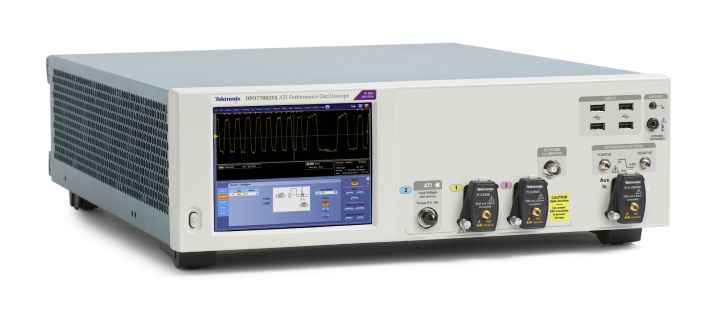
DPO77002SX Key performance specifications
- 70 GHz analog bandwidth, <6 ps=»» rise=»» span=»»>
- time Low-noise ATI architecture
- Industry-leading sample rate and timing resolution
— 200 GS/s, 5 ps/Sample real-time sample rate
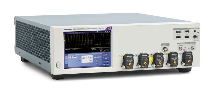
DPO73304SX Key performance specifications
- 33 GHz analog bandwidth
- Industry-leading sample rate and timing resolution
— 100 GS/s, 10 ps/Sample real-time sample rate
Key features
- Superior signal fidelity and excellent signal-to-noise ratio
- Stable and precise multi-channel timing for most accurate analysis
- Compact instrument package with flexibility for future expansion and simple reconfiguration
Introduction
DPO70000SX-series oscilloscopes provide the most accurate real time performance for ultra-bandwidth applications.
- Low noise, 70 GHz real time signal capture using patented ATI architecture
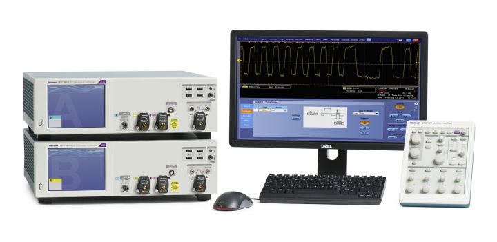
- Compact 5 ¼» (3U) instrument package for the most versatile multi- channel systems
- Precise, scalable performance using UltraSync multi-unit time synchronization bus
- Highest trigger performance with >25 GHz Edge trigger bandwidth, unique new Envelope trigger
Low-noise, high fidelity signal acquisition is critical in ultra-bandwidth applications such as long-haul coherent optical, 400G datacomm and wideband RF. The flagship DPO77002SX model uses ATI (Asynchronous Time Interleaving) architecture to achieve 70 GHz and 200 GS/s (5 ps/ Sample) real time acquisition performance. This patented, symmetric architecture elegantly creates an inherent noise advantage over legacy bandwidth interleaving methods. The DPO70000SX provides the lowest noise, highest fidelity and maximum performance for complex optical modulation analysis, jitter and noise analysis of high speed serial signaling and frequency, phase and modulation analysis of wideband RF signals
Connectivity
- USB host ports on both front and rear panel for quick and easy data storage, printing, keyboard and mouse
- Integrated 10/100/1000 Ethernet port for network connection
- External display interfaces for connection of monitor or projector
Applications
- Coherent optical modulation analysis
- Research and defense data acquisition and analysis.
| Model overview | ||||||
| DPO77002SX | DPO73304SX | |||||
| Single unit | Dual-unit system | Single unit | Dual-unit system | |||
| ATI channel | Non-ATI channels | ATI channel | Non-ATI channels | Non-ATI channels | Non-ATI channels | |
| Analog bandwidth | 70 GHz | 33 GHz | 70 GHz | 33 GHz | 33 GHz | 33 GHz |
| Analog channels | 1 | 2 | 2 | 4 | 4 | 8 |
| Sample rate per channel | 200 GS/s | <100 gs=»» s=»» td=»»> | 200 GS/s | <100 gs=»» s=»» td=»»> | <100 gs=»» s=»» td=»»> | <100 gs=»» s=»» td=»»> |
| Rise time (typical) | 10% to 90%: 5.6 ps 20% to 80%: 4.3 ps | 10% to 90%: 13 ps 20% to 80%: 9 ps | 10% to 90%: 5.6 ps 20% to 80%: 4.3 ps | 10% to 90%: 13 ps 20% to 80%: 9 ps | 10% to 90%: 13 ps 20% to 80%: 9 ps | 10% to 90%: 13 ps 20% to 80%: 9 ps |
| Vertical Noise (% of full scale), bandwidth filter on, max sample rate (typical) | 0.75% of full scale (300 mVFS) (design target) | 0.56% of full scale (500 mVFS) | 0.75% of full scale (300 mVFS) (design target) | 0.56% of full scale (500 mVFS) | 0.56% of full scale (500 mVFS) | 0.56% of full scale (500 mVFS) |
| Record length, points (each channel, standard) | 62.5 M | 62.5 M | 62.5 M | 62.5 M | 62.5 M | 62.5 M |
| Record length (each channel, Opt. 10XL) | 125 M | 125 M | 125 M | 125 M | 125 M | 125 M |
| Record length (each channel, Opt. 20XL) | 250 M | 250 M | 250 M | 250 M | 250 M | 250 M |
| Record length (each channel, Opt. 50XL) | 1 G | 1 G | 1 G | 1 G | 1 G | 1 G |
| Timing resolution | 5 ps (200 GS/s) | 10 ps (100 GS/s) | 5 ps (200 GS/s) | 10 ps (100 GS/s) | 10 ps (100 GS/s) | 10 ps (100 GS/s) |
| Duration at highest sample rate (Standard) | 313 |js | 625 js | 313 js | 625 js | 625 js | 625 js |
| Duration at highest sample rate (Opt. 10XL) | 625 js | 1.25 ms | 625 js | 1.25 ms | 1.25 ms | 1.25 ms |
| Duration at highest sample rate (Opt. 20XL) | 1.25 ms | 2.5 ms | 1.25 ms | 2.5 ms | 2.5 ms | 2.5 ms |
| Duration at highest sample rate (Opt. 50XL) | 5.0 ms | 10 ms | 5.0 ms | 10 ms | 10 ms | 10 ms |
| Vertical system — analog channels | ||||||
| Bandwidth limit | Depending on instrument model: 70 GHz to 1 GHz in 1 GHz steps, or 500 MHz ; 5 GHz steps above 35 GHz 1 | |||||
| Hardware-only bandwidth settings at 33 GHz available on non-ATI channels. No hardware-only settings available on ATI channel. | ||||||
| Channel-to-channel isolation | ||||||
| TekConnect channels | ||||||
| 0 to 9 GHz | ≥ 120:1 isolation | |||||
| >9 to 12 GHz | ≥ 80:1 isolation | |||||
| >12 to 15 GHz | ≥ 50:1 isolation | |||||
| >15 to 20 GHz | ≥ 25:1 isolation | |||||
| >20 to 33 GHz | ≥ 20:1 isolation | |||||
| ATI channel | >120:1 | |||||
| DC gain accuracy | ± 2% | |||||
| Vertical system — analog channels | ||||||
| Delay between channels, fullbandwidth, equivalent time, BWE off typical | < 1 ps between any two channels at any gain setting at 25 °C ±5 °C. | |||||
| Derate linearly to <10 ps=»» at=»» 5=»» c=»» and=»» 45=»» td=»»> | ||||||
| Effective number of bits (typical) | ||||||
| 33 GHz TekConnect Channels | ≥ 5.0 bits at settings >160 mVFS, 24.3 bits at 63.5 mVFS | |||||
| 70 GHz ATI Channel | ≥ 4.8 bits at settings >200 mVFS, 24.2 bits at 100 mVFS | |||||
| Signal-to-Noise ratio (typical) | 34 dB | |||||
| Input coupling | ||||||
| TekConnect channels: | Two modes: DC, 50 ohms to a programmable termination voltage; Ground. The termination can be connected to a DC voltage: ≤1.2 V/FS settings: -3.5 V to 3.5 V, > 1.2 V/FS settings: 0.0 V |
|||||
| ATI channel: | DC, 50 Q. | |||||
| Input resistance | ||||||
| ≤1.2 VFS settings | 50 Q ±3% at 18 to 28 °C (64 to 82 °F) | |||||
| >1.2 VFS settings | 50 Q ±4% over 5 to 45 °C (45 to 113 °F), type tested 50 Q ±4.4% over 5 to 45 °C (45 to 113 °F), type tested | |||||
| Sensitivity range | ||||||
| TekConnect channels | 62.5 mVFS to 6 VFS | |||||
| ATI channel | 100 mVFS to 300 mVFS. | |||||
| Maximum input voltage | ||||||
| TekConnect channels: | s1.2 VFS settings: ±1.5 V relative to the termination bias (30 mA maximum) ±5 V absolute maximum input >1.2 VFS settings: 8 V. Limited by maximum Vterm current and the attenuator power rating at maximum temperature |
|||||
| ATI channel | ± 500 mV RMS and ±0.75 V pk | |||||
| Aux channel: | ±5.0 V | |||||
| Input termination voltage (VTerm) range, TekConnect channels | ||||||
| <1.2 vfs=»» settings:=»» td=»»> | -3.5 V to +3.5 V | |||||
| >1.2 VFS settings: | 0 V | |||||
| Offset accuracy | ||||||
| Full scale voltage range | Offset accuracy | |||||
| 62.5 mVFS to 1.2 VFS 2 | ±(0.4% | net offset | + 0.2% | net offset — Vterm setting | + 2.5 mV + 1% Full Scale) | |||||
| >1.2 Vfs to 6 Vfs | ±(0.6% | net offset | + 13.4 mV + 1% Full Scale) | |||||
| Vertical system — analog channels | ||||||
| Offset range | ||||||
| TekConnect channels | ||||||
| Full Scale voltage range | Offset range | |||||
| 62.5 mVFS — 1.2 VFS | ±3.4 V | |||||
| >1.2 VFS — 6 VFS | ±6 V | |||||
| ATI channel | ||||||
| Full Scale voltage range | Offset range | |||||
| 100 mVFS — 300 mVFS | ±300 mV | |||||
| Frequency response tolerance | ||||||
| All modes, BWE on, typical | ||||||
| Passband flatness with BWE enabled | ||||||
| Spec | P/F limits | |||||
| Passband flatness, All Instruments | Step settings: 77.5 mVFS, 151 mVFS, 302 mVFS, 605 mVFS, 1210 mVFS., 1620 mVFS, 3240 mVFS ±0.5 dB from DC to 50% of nominal BW. ±1.5 dB from 50% to 80% of nominal BW. All other gain settings: ±1.0 dB from DC to 50% of nominal BW ±2.0 dB from 50% to 80% of nominal BW | |||||
| Position range | ± 5 divisions | |||||
| Vertical resolution | 8 bits, (11 bits with averaging) | |||||
| Horizontal system | ||||||
| Channel-to-Channel deskew range | ±75 ns | |||||
| Time base accuracy | ± 1.0 ppm initial accuracy. Aging < 0.5 ppm per year. Applies only when using the internal reference. | |||||
| Time base delay time range | -5.0 ks to 1.0 ks | |||||
| Sample Clock Jitter | <5 span=»» class=»font5″>µ Duration: 65 fsRMS | |||||
| Trigger jitter | 100 fs using enhanced trigger placement. | |||||
| Acquisition System | ||||||
| Acquisition modes | ||||||
| Sample | Acquires and displays sampled values | |||||
| Average | From 2 to 10,000 waveforms can be included in an average waveform | |||||
| Envelope | From 1 to 2*109 waveforms included in min-max envelope | |||||
| Hi-Res | Real-time boxcar averaging reduces random noise and increases resolution | |||||
| Peak detect | Capture and display narrow glitches at all real-time sampling rates. Glitch widths: 1 ns at <125 ms=»» s=»» 1=»» sample=»» rate=»» at=»» a250=»» td=»»> | |||||
| FastAcq® | FastAcq® optimizes the instrument for analysis of dynamic signals and capture of infrequent events, capturing >300,000 wfms/s on all TekConnect channels simultaneously, standalone configuration only | |||||
| FastFrame® | Acquisition memory divided into segments; maximum trigger rate >310,000 waveforms per second. Time of arrival recorded with each event. Frame finder tool helps to visually identify transients. TekConnect channels only, standalone configuration only | |||||
| Roll mode | Scrolls sequential waveform points across the display in a right-to-left rolling motion. Works at sample rates up to 10 MS/s with a maximum record length of 40 MS. TekConnect channels only, standalone configuration only | |||||
| Waveform database | Accumulates waveform data providing a three-dimensional array of amplitude, time, and counts. TekConnect channels only, standalone configuration only | |||||
| Pinpoint® Trigger system | ||||||
| Trigger sensitivity | ||||||
| A Event trigger, B Event trigger | ||||||
| Internal DC coupled | ≤5%FS from DC to 50 MHz ≤7.5%FS at 5 GHz ≤10%FS at 10 GHz ≤15%FS at 15 GHz ≤35%FS at 20 GHz ≤60%FS at 25 GHz |
|||||
| Aux input 50 Q (external trigger) | ||||||
| Auxiliary input | 100 mVpp from DC to 1 GHz 175 mVpp at 4 GHz 225 mVpp at 8 GHz 325 mVpp at 10 GHz 800 mVpp at 12 GHz |
|||||
| Edge trigger sensitivity not DC coupled, typical | ||||||
| All sources, positive or negative edge, for vertical scale settings a 10 mV/div and <1 v=»» div=»» td=»»> | ||||||
| Trigger Coupling | Sensitivity | |||||
| NOISE REJ | 15%FS from DC to 50 MHz 22.5% at 5 GHz 30%FS at 10 GHz 45%FS at 15 GHz 100%FS at 20 GHz | |||||
| AC | Same as DC-coupled limits for frequencies > 100 Hz, attenuates signals <100 hz=»» td=»»> | |||||
| HF REJ | Same as DC-coupled limits for frequencies < 20 kHz, attenuates signals > 20 kHz | |||||
| LF REJ | Same as DC-coupled limits for frequencies > 200 kHz, attenuates signals < 200 kHz | |||||
| Pinpoint® Trigger system | ||||||
| A event and delayed B event trigger types | ||||||
| Standalone instrument | DPO73304SX | DPO77002SX | ||||
| Trigger type | Standard channel | ATI channel | Standard channel | |||
| Edge | X | X | X | |||
| Glitch | X | X | X | |||
| Width | X | X | X | |||
| Runt | X | X | X | |||
| Window | X | X | X | |||
| Timeout | X | X | X | |||
| Period/Frequency | X | X | X | |||
| envelope | X | X | X | |||
| Transition | X | X | X | |||
| Logic Pattern | X | X | ||||
| Setup/Hold | X | X | ||||
| Low speed serial | X | X | X | |||
| Logic state | X | |||||
| Multi-unit configuration | DPO73304SX | DPO77002SX | ||||
| Trigger type | Standard channel | ATI channel | Standard channel | |||
| Edge | X | X | X | |||
| Glitch | X | X | X | |||
| Width | X | X | X | |||
| Main trigger modes | Auto, Normal, and Single | |||||
| Trigger sequences | Main, Delayed by Time, Delayed by Events, Reset by Time, Reset by State, Reset by Transition. All sequences can include a separate horizontal delay after the trigger event to position the acquisition window in time | |||||
| Trigger coupling | DC, AC (attenuates <100 hz=»» br=»»> HF Rej (attenuates >20 kHz) LF Rej (attenuates <200 khz=»» noise=»» reject=»» reduces=»» sensitivity=»» td=»»> |
|||||
| Variable A event trigger holdoff range | 250 ns to 12 s + random holdoff | |||||
| Trigger level or threshold range | ||||||
| Trigger Source | Range | |||||
| Ch1, 2, 3, or 4 | Full scale | |||||
| Auxiliary input | ±3.65 V | |||||
| Line | 0 V, Not settable | |||||
| Enhanced triggering | Enhanced triggering corrects the difference in timing between the trigger path and the acquired data path (supports all Pinpoint trigger types on both A- and B-Events except pattern trigger); Default On (user-selectable); Not available in FastAcq mode. | |||||
| Line trigger | Trigger on power line signal. Level fixed at 0 V. | |||||
| Pinpoint® Trigger system | ||||||
| Visual Trigger | Requires Option VET | |||||
| Max number of areas | 8 | |||||
| Area shapes Compatibility | Rectangle, Triangle, Trapezoid, Hexagon, user defined shapes (can have >40 vertices) | |||||
| Compatibility | Visual Trigger qualification is compatible with all trigger types and all trigger sequences | |||||
| Trigger type | Description | |||||
| Edge | Positive or negative slope on any channel or front-panel auxiliary input. Coupling includes DC, AC, noise reject, HF reject, and LF reject. | |||||
| Frequency/Period | Trigger on event that crosses threshold twice with same slope within or outside of selectable time limits. Slope may be positive, negative or either. | |||||
| Glitch | Trigger on or reject glitches of positive, negative, or either polarity. Minimum glitch width is 40 ps (typical) with rearm time of 50 ps (<5 ns=»» interva=»» 75=»» ps=»» above=»» 5=»» td=»»> | |||||
| Pattern | Trigger when pattern goes false or stays true for specified period of time. Pattern (AND, OR, NAND, NOR) specified for four input channels. | |||||
| Runt | Trigger on a pulse that crosses one threshold but fails to cross a second threshold before crossing the first again. Event can be time- or logic-qualified. Minimum runt width is 40 ps (typical) with rearm time of 50 ps | |||||
| Setup/Hold | Trigger on violations of both setup time and hold time between clock and data present on any two input channels. | |||||
| State | Any logical pattern of channels (1, 2, 3) clocked by edge on channel 4. Trigger on rising or falling clock edge. | |||||
| Timeout | Trigger on an event which remains high, low, or either, for a specified time period. Selectable from 300 ps. | |||||
| Transition | Trigger on pulse edge rates that are faster or slower than specified. Slope may be positive, negative, or either. | |||||
| Width | Trigger on width of positive or negative pulse either within or out of selectable time limits (down to 40 ps). | |||||
| Window | Trigger on an event that enters or exits a window defined by two user-adjustable thresholds. Event can be time or logic qualified. | |||||
| Visual Trigger | Trigger when the Visual Trigger expression is satisfied. | |||||
| Envelope | Qualification applied to Edge, Glitch, Width or Runt trigger such that trigger type is performed on the detected envelope of a modulated carrier. Carrier frequency 250 MHz to 15 GHz. Minimum burst width <20 ns=»» maximum=»» gap=»» between=»» bursts=»» 20=»» td=»»> | |||||
| Trigger modes | ||||||
| Trigger mode | Description | |||||
| Trigger Delay by Events | 1 to 2 billion events. | |||||
| Trigger Delay by Time | 3.2 ns to 3 million seconds. | |||||
| B Event Scan | B Event Scan is an A to B trigger sequence that will trigger and capture burst event data of interest as defined in the B Event Scan setup menu. Captured bits can be scanned in a sequential or randomized fashion, and alternatively the trigger can toggle between two successive B trigger events. Eye diagrams can be constructed with burst data acquired as a result of scanning B Event. | |||||
| Search and Mark Events | Search for edges, glitches, or pulses of specified width. Any events found matching the search criteria are marked and placed in the Event table. The search can use positive/negative slopes or both on any channels. | |||||
| When an event of interest is found, other similar events can be found using «Mark All Trigger Events in Record» in the Pinpoint trigger control windows. | ||||||
| The Event table summarizes all found events. All events are time stamped in reference to trigger position. Users can choose to stop acquisitions when an event is found. | ||||||
| Waveform measurements | ||||||
| Automatic measurements | 53, of which 8 can be displayed on-screen at any one time; measurement statistics, user-definable reference levels, measurement within gates isolating the specific occurrence within an acquisition to measure The DPOJET Jitter and Eye Analysis application offers additional automated and advanced measurements such as jitter. | |||||
| Amplitude related | Amplitude, High, Low, Maximum, Minimum, Peak-to-Peak, Mean, Cycle Mean, RMS, Cycle RMS, Positive Overshoot, Negative Overshoot | |||||
| Time related | Rise Time, Fall Time, Positive Width, Negative Width, Positive Duty Cycle, Negative Duty Cycle, Period, Frequency, Delay | |||||
| Combination | Area, Cycle Area, Phase, Burst Width | |||||
| Histogram related | Waveform Count, Hits in Box, Peak Hits, Median, Maximum, Minimum, Peak-to-Peak, Mean (|j), Standard Deviation (sigma), |j +1sigma, |j +2sigma, |j +3sigma | |||||
| Waveform processing/math | ||||||
| Algebraic expressions | Define extensive algebraic expressions including Waveforms, Scalars, User-adjustable Variables, and Results of Parametric Measurements e.g. (Integral (CH1 — Mean(CH1)) x 1.414 x VAR1) | |||||
| Arithmetic | Add, Subtract, Multiply, Divide Waveforms and Scalars | |||||
| Filtering function | User-definable filters. Users specify a file containing the coefficients of the filter. Several example filter files are provided | |||||
| Frequency domain functions | Spectral Magnitude and Phase, Real and Imaginary Spectra | |||||
| Mask function | Generates a Waveform Database pixel map from a sample waveform. Sample count can be defined | |||||
| Math functions | Average, Invert, Integrate, Differentiate, Square Root, Exponential, Log 10, Log e, Abs, Ceiling, Floor, Min, Max, Sin, Cos, Tan, ASin, ACos, ATan, Sinh, Cosh, Tanh | |||||
| Relational | Boolean result of comparison >, <, a=»» td=»»> | |||||
| Vertical units | Magnitude: Linear, dB, dBm Phase: Degrees, radians, group delay IRE and mV units | |||||
| Window functions | Rectangular, Hamming, Hanning, Kaiser-Bessel, Blackman-Harris, Gaussian, Flattop2, Tek Exponential | |||||
| Customized Functions using Math Plug-in Interface | An interface is provided to allow users to create their own custom math functions in MATLAB or Visual Studio | |||||
| Display system | ||||||
| Color palettes | Normal, Green, Gray, Temperature, Spectral, and User-defined | |||||
| Format | YT, XY, XYZ | |||||
| Display resolution | 1024 horizontal x 768 vertical pixels (XGA) | |||||
| Display type | 6.5 in. liquid-crystal active-matrix color display | |||||
| Horizontal divisions | 10 | |||||
| Vertical divisions | 10 | |||||
| Waveform styles | Vectors, Dots, Variable Persistance, Infinite Persistance | |||||
| Computer system and peripherals | ||||||
| Operating system | Microsoft Windows 7 Ultimate — 64 bit OS | |||||
| CPU | INTEL CORE I7-4970S, 3.9 GHz, QUAD CORE | |||||
| System memory | 32 GB | |||||
| Solid state drive | Removable, 960 GB capacity | |||||
| Mouse | Optical wheel mouse, USB interface | |||||
| Keyboard | USB interface | |||||
| Input-output ports | ||||||
| Auxiliary trigger input characteristics and range | 50 Q, ±5 V (DC plus peak AC) | |||||
| Auxiliary output logic polarity and functionality | Default output is A trigger low true (a negative edge when the A trigger event occurs). You can also program the output to A trigger high true, B trigger low or high true, disabled, force high, and force low. | |||||
| Fast Edge output step amplitude and offset | 1100 mV differential into a 100 Q load with a -300 mV common mode. 30 ps rise and fall times. | |||||
| 550 mV ±100 mV swing per side into a 50 Q load. | ||||||
| External reference input frequency, typical | 10 MHz, 100 MHz, 12.5 GHz | |||||
| The instrument scans for either 10 MHz or 100 MHz. 12.5 GHz supported on separate SMA input. | ||||||
| 12.5 GHz Clock In | 1.4 Vp-p (7.0 dBm) | |||||
| 12.5 GHz Clock Out | 2.0 Vp-p (10 dBm) | |||||
| Internal reference output voltage, typical | ||||||
| 10 MHz Vout pk-pk | > 800 mV peak-peak into 50 Q | |||||
| > 1.6 V peak-peak into 1 MQ (internally AC coupled). | ||||||
| 12.5 GHz Vout | >10 dBm | |||||
| Input and output ports | ||||||
| DVI-D Video port | A female Digital Visual Interface (DVI-D) compatible port | |||||
| VGA port | A female Video Graphics Array (VGA) compatible port | |||||
| Display port | Two connectors (primary, secondary) provide digital display interfaces | |||||
| PCIe | PCIe port to connect external devices or to configure multi-instrument systems. | |||||
| Trigger | UltraSync trigger bus. | |||||
| Keyboard and Mouse ports | PS-2 compatible, instrument must be powered down to make connection | |||||
| LAN port | Two RJ-45 connectors (LAN1, LAN2), support 10 base-T, 100 base-T, and Gigabit Ethernet | |||||
| External audio ports | External audio jacks for microphone input and line output | |||||
| USB ports | Four front panel USB 2.0 connectors. | |||||
| Four rear panel USB 3.0/USB 2.0 connectors. | ||||||
| One rear panel USB device connector. | ||||||
| Data storage specifications | ||||||
| Nonvolatile memory retention time, typical | >20 years | |||||
| Solid state drive | Waveforms and setups are stored on the solid state drive. Solid state drive is a a960 GB solid state drive. |
|||||
| Power source | ||||||
| Power consumption | <1200 va=»» td=»»> | |||||
| Source voltage and frequency | 100 V to 240 VRMS, 50/60 Hz 115 V ±10%, 400 Hz CAT II |
|||||
| Mechanical specificationsContainer | ||||||
| Dimensions | ||||||
| DPO70000SX models | 157 mm (6.0 in) height 452 mm (17.8 in) width 553 mm (21.8 in) depth |
|||||
| DPO70000SX models, Rackmount configuration | 177 mm (7.0 in) height 440 mm (19.75 in) width 523 mm (20.6 in) depth (from rack mounting ear to back of instrument) |
|||||
| Weight | ||||||
| DPO70000SX models | 19 kg (42 lbs) oscilloscope only | |||||
| Cooling | ||||||
| Required clearances | ||||||
| Fan-forced air circulation with no air filter | ||||||
| Top | 0 mm (0 in) | |||||
| Bottom | 6.35 mm (0.25 in) minimum or 0 mm (0 in) when standing on feet, flip stands down | |||||
| Left side | 76 mm (3 in) | |||||
| Right side | 76 mm (3 in) | |||||
| Rear | 0 mm (0 in) on rear feet | |||||
| Environmental specifications | ||||||
| Temperature | ||||||
| Operating | 5 °C to +45 °C | |||||
| Nonoperating — | 20 °C to +60 °C | |||||
| Humidity | ||||||
| Operating | 8% to 80% relative humidity at up to +32 °C (+90 °F) 5% to 45% relative humidity above +32 °C (+90 °F) up to +45 °C (+113 °F), noncondensing, and is limited by a maximum wet-bulb temperature of +29.4 °C (+85 °F) (derates relative humidity to 32% at +45 °C (+113 °F) |
|||||
| Nonoperating | 5% to 95% relative humidity at up to +30 °C (+86 °F), 5% to 45% relative humidity above +30 °C (+86 °F), up to +60 °C (+140 °F), noncondensing, and is limited by a maximum wet-bulb temperature of +29.4 °C (+85 °F) (derates relative humidity to 11% at +60 °C (+140 °F)) |
|||||
| Environmental specifications | ||||||
| Altitude | ||||||
| Operating | Up to 3,000 meters | |||||
| Nonoperating | Up to 12,000 meters | |||||
| United States Government | Tektronix has tested the DPO70000SX Series oscilloscopes for compatibility with the security configuration for Information | |||||
| Configuration Baseline (USGCB) Testing | Technology products specified in the USGCB settings for Windows 7 and Internet Explorer | |||||
| Regulatory | ||||||
| Electromagnetic compatibility | 2004/108/EC; EN 61326-2-1 | |||||
| Certifications | UL 61010-1, CSA 61010-1-04, LVD 2006/95/EC, EN61010-1, IEC 61010-1 | |||||